Rasterization Pattern
Every GPU has its own set of rules during rasterization phase i.e. how to form macro tiles from triangle fragments, how to traverse them, how to setup the grid. One of very important aspect of this complex phase is the actual order or pattern of execution. Visually if there would not be any double buffering we would see GPU sequentially (actually multiple in parallel) filling up small pixel tiles in our buffer in a specific order that should technically help rendering performance.
In case of AMD GCN we know that whatever we throw at hardware it will try to work out something at 64 unit granularity (which can be tiled in blocks, lines etc.) – due to the fact that this architecture is dealing with so called ‘wavefronts’. In case of Pixel Shaders, rasterizer forms tiles in quads and tiles of size 8×8. This time around I am not going to delve deeper into actual algorithms behind tile creation.
Why does it matter?
As mentioned previously, pattern is supposed to help the GPU to render things faster.
When looking at a rasterization pattern in 2D, first thing that jumps into mind is its spatial coherence. This is closely related to caching.
The slowest part of every graphic hardware is the memory, therefore we have to rely heavily on GPU L1/L2 caching units. Caches work using specific use patterns that vary depending on the use case. 3D textures would hint the cache to pre-load the 3D spatial neighbourhood of current sampling point. 2D would hint the same but in 2 dimensional plane. A 2D mip mapped texture would also suggest precaching spatial direction using sample uv derivatives that could stretch into 3rd dimension, going through mip map chain.
Obviously caches are limited in memory therefore we would preferably like to pre-cache data that can be reused as much as possible. Therefore we can expect the rasterizer pattern to respect that locality constraint.
Another performance constraint having order dependency comes from Z buffer. The most efficient way is to render front to back, as Z buffer can early reject most pixels that would be covered by those in front. A really smart rasterizer should try to take care of this (but that would be very hard to implement cost efficient in consumer hardware).
To sum up we are looking at:
- spatial cache coherency
- depth ordering
So how does our AMD GCN fare there?
Full Screen Pass
For simplicity let’s just assume we are dealing with a full screen pass, which most engines tend to execute using a quad composed of two triangles covering (0,0) (0,1) (1,0) (1,1) viewport space (due to some legacy hw handling of scissor test – looking at you X360 and PS3). Another, more modern way is to render just one triangle at (0,0) (2,0) (0,2) that would span over whole viewport and rely on clipping / scissor unit to do the job.
In almost every case our screen resolution will be bigger than 8×8 tile. So the question is how the HW will subdivide our triangles into tiles, schedule them and execute – and why would that even matter? And would there be a difference between same shader executing in Pixel Shading pipeline and Compute Shader pipeline (tile execution pattern wise)
Pixel Shader
Let’s start with Pixel Shader.
Experience with multiple previous generations of hardware would suggest some simple rasterization pattern such as Left-Right Top-Bottom (some Nvidia GPUs), Swizzle Top Down (some AMD GPUs) or interleaved (various more exotic GPUs). Obviously we could expect this to be micro-tiled in 8×8 pixel groups for AMD GCN.
From HW spec we also know that GCN architecture is capable of issuing multiple primitives in parallel splitting them between multiple wavefront. In that case Z ordering might matter in a ‘stochastic’ average case (we can’t expect the GPU to see actual savings in ordering fragments executed in parallel, however after a certain amount of cycles, and fragments rendered, Z caches should be updated to be able to reject something – therefore it would always be beneficial to push front fragments first).
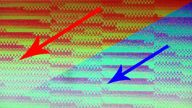
So let’s render a full screen triangle first. We do it @720p on one of more ‘exotic’ and my favorite GCN derivatives (sorry for the quality, due to some technical issues had to take a photo – and don’t mind top left corner – evil things happened there).

This image can be read as follows : colour rise with every 64 pixels completed (this visualizes nicely as 8×8 micro tiles). Red goes and wraps first, then green than blue. In this particular image we can see that Pixel Shader Rasterization happens in 512×32 bands roughly scanned top – bottom of primitive – where thread groups are issued in Z order of the covering tile. This triangle was slightly skewed towards top right corner in camera direction – therefore we can see that bands tend to follow right-left / diagonal direction.
In another test I tried top left skewed and it seemed to change the band order to be opposite proving the point (still would be nice to have official confirmation somewhere).
This has a big advantage – giving ZBuffer culling units to ‘stochastically’ catch up with incoming fragments as those ‘might be sorted’ by Z – which is a really cool feature by its own, also showing GCN really good performance in triangle soups scenario (putting your camera inside a multi triangle bush has never been that easy!).
So we can see that rasterizer actually follows two main constraints : spatial locality and z-order.
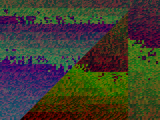
Unfortunately that doesn’t seem to be great for our legacy 2 triangle quad. As the triangles will probably get traversed in large macro tiles, we can expect execution order to follow left triangle top-bottomn first and then second triangle top-bottom again.
What that would mean is that locality constraint would be absolutely broken the very moment right triangle fragments start rasterizing.
This would seriously hurt the cache when approaching bottom left and then switching to upper right. We can predict that whole cache would have to be invalidated as there is absolutely no common data between those two execution points.
Running this shader on pixel quad composed of two triangles proves this assumption (again sorry for lack of real screenshots – hardware fault, but feel free to check G-Truc excellent post on similar matter and another GCN derivative hardware (similar behaviour).
We can imagine this is bad if our shader relies on cache efficiency. How bad? We will see in a second.
First let’s check how the Compute Pipeline would behave.
Compue Shader
First let’s try an empty Compute Shader dispatched by X,Y,1 (flat Z).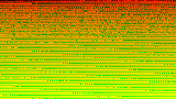
We see that about 30% of first groups are random due to startup latency. Then when all catches up and provides really nice sequential reading in X,Y,Z (Z=1) order, Left-Right, Top-Bottom scanning.
Now let’s try something rather complex on latency and cache behaviour. One of my custom SSAO implementation (wide random radius, expected latency and cache dependency, very high utilization and load).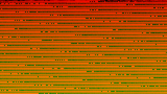
Behaviour has changed. As you can see under load dispatches are ‘scanning’ the work area spatially Left to Right, Top to bottom guaranteeing very good cache coherency. Also we can see excellent continuity under high load as well as GCN ability to reschedule group execution based on latency – therefore several groups in line seem to be ‘misplaced’ – this shows the ability of HW to hide latency (where in a case of latency – a group can just wait for its turn).
Knowing SSAO sampling pattern it’s actually easy (knowing which group corresponds to which timestamp, that you can;t unfortunately that clearly see from this image without additional data) to see that last row of pixels from SSAO (ones that are sampling new cache lines ‘lower’ than current execution) need to wait a bit for the data to load, whereas other groups that are on the ‘right’ have higher chance of data ‘incache’ so they can execute faster. This SSAO was set to be very greedy on sampling pattern to force this kind of behaviour.
Does it matter?
Well why would I spend my life doing this if it wouldn’t matter ; )
I was investigating weird L1/L2 cache coherency issues in some post processing pipeline that was adapted from old gen engine, where full screen effects were drawn as 2 triangles. All in all numbers I was seeing didn’t make much sense in my use case (slower by 10%).
After investigation it seemed that 2 triangles were permitting the shader to run at full speed.
A quick comparison between 2 triangle, 1 triangle and compute method gave me following results on cache efficiency:
- 2 Triangle Quad Pixel Shader : 87% L1/L2 hit ratio
- 1 Full screen Triangle Pixel Shader : 95% :L1/L2 hit ratio
- Compute Shader : 95% : L1/L2 hit ratio
Those results were invariant and repeatable in that particular shader. Sampling behaviour was uniform random distribution in circle (think poisson sampling).
Then another test was carried out with a different sampling behaviour that prioritizing wide lanes (think horizontal blur). In that case numbers were also similar with CS getting ahead of the rest (due to long lanes left – right scanning).
Cache hit ratio directly impacted performance which in the end scaled as follow in 3 average cases (multiple different sampling patterns).
- 2 Triangle Quad Pixel Shader : 100% performance
- 1 Full screen Triangle Pixel Shader : 108% performance
- Compute Shader : 108% performance (more sensitive to sampling patterns than PS)
Please note that both CS and PS were outputting to RWTexture2D instead of MRT, to provide same setting for testing. Otherwise PS would have unfair advantage as cache lines would not get polluted by RWTexture output (as ROP output has it’s own output caches orthogonal to L1/L2) – however whole discussion of PS vs CS in full screen passes is a totally different topic (where PS is mostly faster unless you can use LDS to your benefit – or special features of CS).
Use that Triangle!
So to summarize know you rasterizer patterns and use them to have best caching coherency. This might seem an overkill – but for me personally almost 10% of performance is a lot and can easily stack up in your post processing pipeline (assuming shaders are cache bound). In my optimization use case it shaved off almost 0.1ms @720p from one shader and perfectly scales with resolution.
Just keep it in mind and let those old habits die.
Then if you have time just set your execution ordering to follow sampling pattern – or go and use much smarter solutions such as interleaved rendering / sampling.
Another important takeaway is that AMD GCN has a benefit of ‘stochastic’ sorting by depth which helps as long as you can help your rasterizer – (rendering shells and layers? Order outside to inside).
